1. Introduction
Keplerian Space Discovery is a spaceflight simulation game in which you assemble rockets, launch them and place them into orbit, set in the real Solar System with real launch sites from around the world. The motion of celestial bodies and spacecraft is calculated from Keplerian orbital mechanics.
2. Quick Start
When you start a new game, a tutorial guides you from the camera controls through to your first rocket launch. It highlights where to click next, so following it is the recommended way to play for the first time.
Your First Goal
In the tutorial you take on the contract "Take a first step", assemble a simple rocket and reach an altitude of 15 km. The main steps are as follows.
- Try rotating, zooming and panning the camera, and resetting its position.
- Take on the contract "Take a first step" from "Contract Management".
- In the "Vehicle Assembly Building", combine an engine, a tank and a nose cone, then save the vehicle.
- Select Kepler Space Center and move the vehicle to the launch pad from "Launch Preparation".
- Start the automatic launch with "LAUNCH", and claim the contract reward once you reach an altitude of 15 km.
That covers the basic flow of the game. Complete contracts to earn rewards, develop new vehicles, and aim for higher altitudes and orbital flight.
3. Main Screen
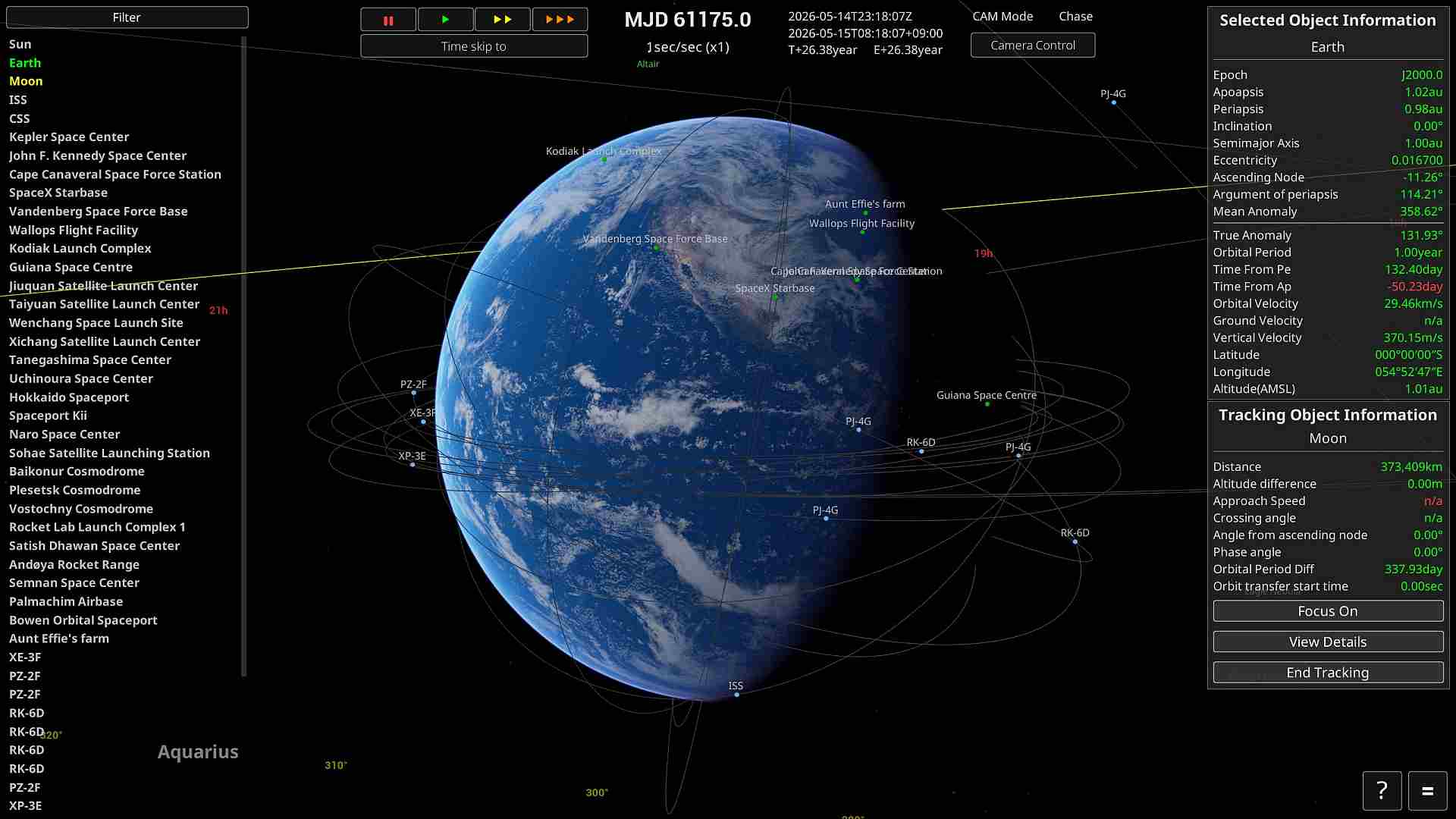
Object Selector
Left-click an entry in the list on the left of the screen to change which object is selected.
Middle-click an object to set it as your tracking target.
Time Controls
- Time acceleration becomes available at altitudes of 1 km and above.
- "||" pauses time, "▶" is real time, and "▶▶▶" is ×10 speed.
- "▶▶▶" can be pressed repeatedly to stack the effect. Each press multiplies the rate by 10, so pressing it three times gives ×1000 speed.
- The rate is capped by a limit that depends on your situation, and never goes above it. Inside the atmosphere or while the engine is burning, for example, the limit is ×4, so pressing "▶▶▶" only takes you to ×4. For the limits, see "Time Acceleration Rules".
Spacecraft Controls
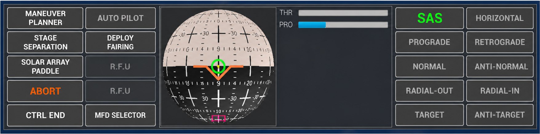
Selecting a controllable spacecraft opens the spacecraft control panel. The panel brings together the controls you need in flight, such as SAS (Stability Augmentation System), attitude targets and stage separation.
To fly the spacecraft yourself, switch to control mode. For throttle and attitude keys, see "Manual Control", and for the individual SAS modes see "SAS (Stability Augmentation System)".
Selected Object Information
The top right of the screen shows information about the currently selected celestial body, spacecraft or ground facility. The selected object is what the camera looks at, and when a spacecraft is selected it also becomes the reference for flight controls and for the time acceleration limit.
For celestial bodies and objects in orbit you can check orbital data such as apoapsis and periapsis, semi-major axis, eccentricity, inclination, orbital period and speed. Near the ground, latitude, longitude and altitude above sea level are shown, and for spacecraft the speeds and altitudes appropriate to the current phase of flight are shown as well. Which items appear depends on the type of object.
Tracking Object Information
When you set a tracking target, information relative to the selected object appears at the bottom right of the screen. Distance, altitude difference, approach speed, crossing angle, phase angle and similar values let you judge a rendezvous or close approach. Items that cannot be calculated are shown as n/a.
The buttons work as follows.
| Focus On | Switches the camera focus to the tracking target. |
| View Details | Opens detailed information about the tracking target. |
| End Tracking | Stops tracking the current target. |
Middle-click a celestial body or spacecraft, or press the O key, to start tracking it.
Filter
Open Filter at the top of the Object Selector to choose which non-celestial objects, such as spacecraft and ground facilities, are shown or hidden. Hidden objects are removed from the Object Selector and from the markers on screen, and the setting is stored in your save data.
Objects that are not yet available in your progress, or whose scheduled launch time has not been reached, do not appear in the filter list at all.
Camera Controls
Camera settings can be opened from Camera Control at the top of the screen. The basic controls are right-drag to rotate, middle-drag to pan, and the mouse wheel to move closer or further away. Press V (or the middle button together with the right button) to switch camera mode.
| Mode | Description |
|---|---|
| Chase | The standard camera, which follows the selected object. |
| Free | Lets you adjust the camera direction and roll freely. |
| Orbital | Switches to a distance and angle that make the whole orbit easy to see. Not available while a ground facility is selected. |
Home / End also move the camera closer and further away, and I / K / J / L also rotate it. Page Up / Page Down adjust the field of view, and Insert / Delete adjust the exposure. For every control, see "Control Keys".
Reading the NavBall
The NavBall shows the attitude of the spacecraft and a set of reference directions on a sphere. Prograde is the direction of travel and Retrograde is its opposite; Normal / Antinormal are perpendicular to the orbital plane; Radial-Out / Radial-In point straight up and straight down as seen from the parent body (Zenith / Nadir). Target / Antitarget point toward the tracking target and away from it, and Maneuver is the burn direction you have set.
Velocity-based markers such as Prograde and Retrograde are referenced to airspeed before orbital insertion, and to inertial velocity after it. Orbital insertion is judged to have happened when the periapsis altitude rises above the parent body's atmospheric boundary (the Karman line). The same switch applies to the SAS attitude targets and to the reference frame used to draw the orbit lines.
For what each direction is used for, see "SAS (Stability Augmentation System)".
Map View
Press M to switch to Map View (the Orbital camera), which shows the whole orbit of the selected object in a wide field of view. Press M again to return to the normal Chase camera. On a hyperbolic trajectory the display range is based on the parent body's SOI, and Map View is not available while a ground facility is selected.
Map View is where you plan a flight, checking the shape of the orbit, the apoapsis and periapsis, and the positions of other objects. For the way the orbit line reference frame changes at orbital insertion, see "Reading the Orbit Lines".
Reading the Orbit Lines
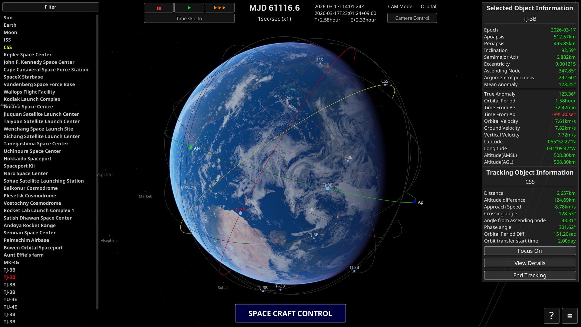
Two kinds of orbit line are drawn on screen.
- Planned orbit … the path you are about to fly, calculated from your current position and velocity. While the engine is burning, its shape changes from moment to moment as you accelerate.
- Actual orbit … a record of the path you have actually flown (your flight trail).
How the orbit lines are drawn changes automatically with the phase of flight.
| State | How it is drawn |
|---|---|
| During launch or ballistic flight (before orbital insertion) | Drawn fixed to the ground. The base of the trail stays at the launch pad, so you can read the path over the ground including the body's rotation — in other words, where you would come down if you kept flying like this. |
| After orbital insertion | Drawn fixed in inertial space. The shape of the orbit itself (an ellipse) is shown, independent of the body's rotation. |
The switch happens "when the periapsis altitude rises above the atmospheric boundary (the Karman line)", which is the same test used for orbital insertion. At the same moment, the reference for the Prograde and other markers on the NavBall changes from airspeed to inertial velocity as well.
When the orbit lines of several objects overlap, you can tell them apart by colour.
| Orbit line colour | Object |
|---|---|
| Green | The currently selected celestial body or spacecraft |
| Yellow | The tracking object |
| Red | The object the pointer is over, in the object list on the left or on a marker on screen |
| Other | Objects that are neither selected, tracked, nor hovered |
SOI Display
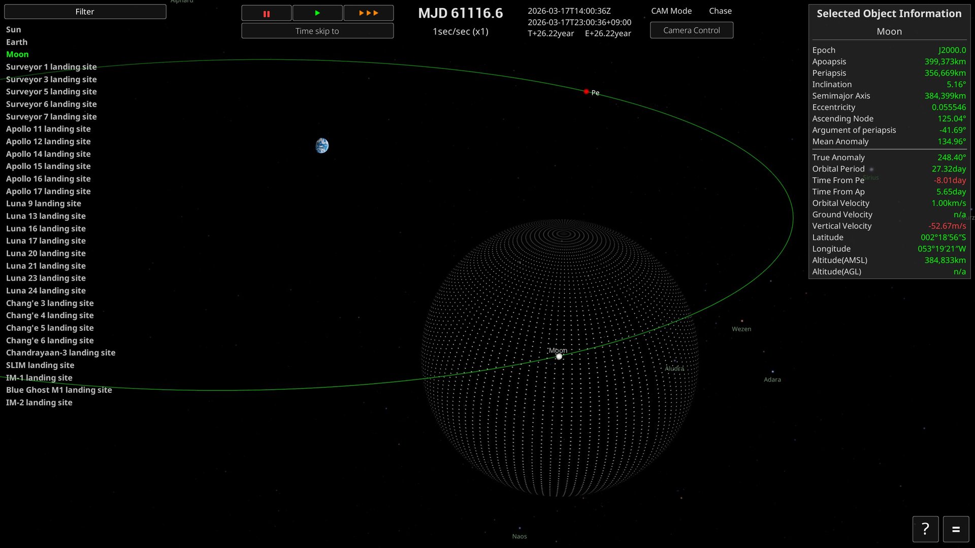
Press F3 to toggle the SOI (Sphere of Influence) display. The SOI is the region within which a body is treated as the central body for a spacecraft's orbit calculation.
In the screenshot above the Moon is selected: the sphere of dots surrounding it is its SOI, and the green line is the orbit of the selected Moon.
When a spacecraft leaves the SOI of its current parent body, it moves onto an orbit centred on a higher body. Conversely, entering the SOI of another body such as a moon or a planet switches it to an orbit centred on that body. On interplanetary or trans-lunar flights, checking where the SOI boundary meets your planned orbit makes the route much easier to follow.
4. Vehicle Assembly Building
In the Vehicle Assembly Building (VAB) you combine parts to design and save rockets of your own.
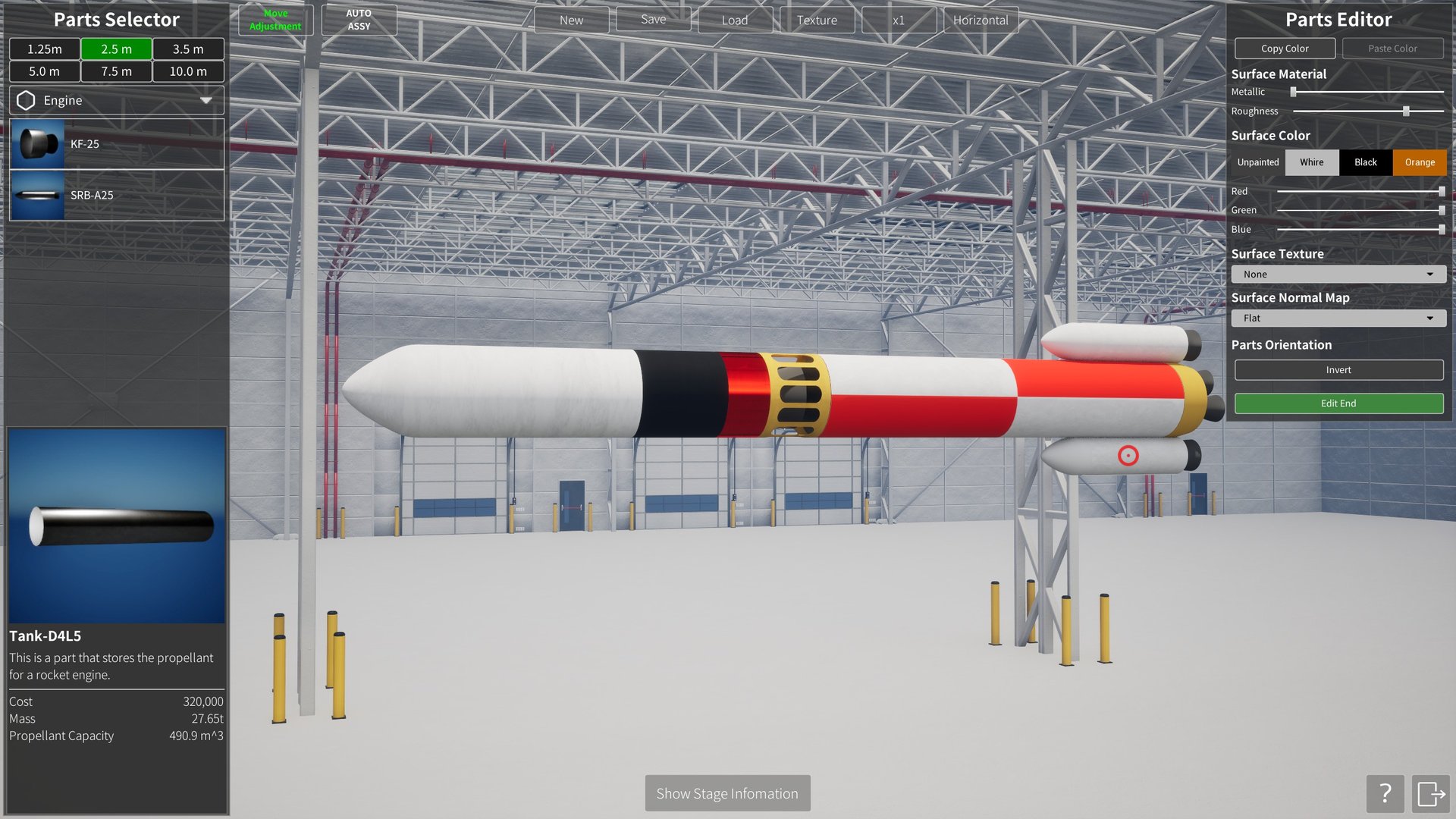
Basic Operations
Placing a part
- Left-click the part you want in the Parts Selector on the left of the screen.
- Release the button after clicking, then move the mouse to drag the part to where you want it (you do not hold the button down).
- Click again at the position you want, and the part is placed there.
- If you place a part near one that is already positioned, it snaps into place and connects automatically.
The diameter tabs at the top of the Parts Selector (1.25 m / 2.5 m / 3.5 m / 5.0 m / 7.5 m / 10.0 m) filter the list to parts of that diameter. The drop-down below them (Engine and so on) switches between part categories such as Tank and Fairing.
Moving a placed part
Parts that are already placed are picked up the same way as new ones: left-click to grab, move with the button released, and left-click again to fix the new position. If you grab a connected part, every child part attached beyond it moves with it.
Connecting parts
Bring a part you are moving into contact with another part, and it is connected automatically with that part as its parent. Placing a part near the centreline of the vehicle snaps it to the axis, which keeps tanks and engines neatly aligned.
Parts left detached from the vehicle are not counted as part of a valid design. When you save, only the valid parts connected back to the root part are stored.
Deleting a part
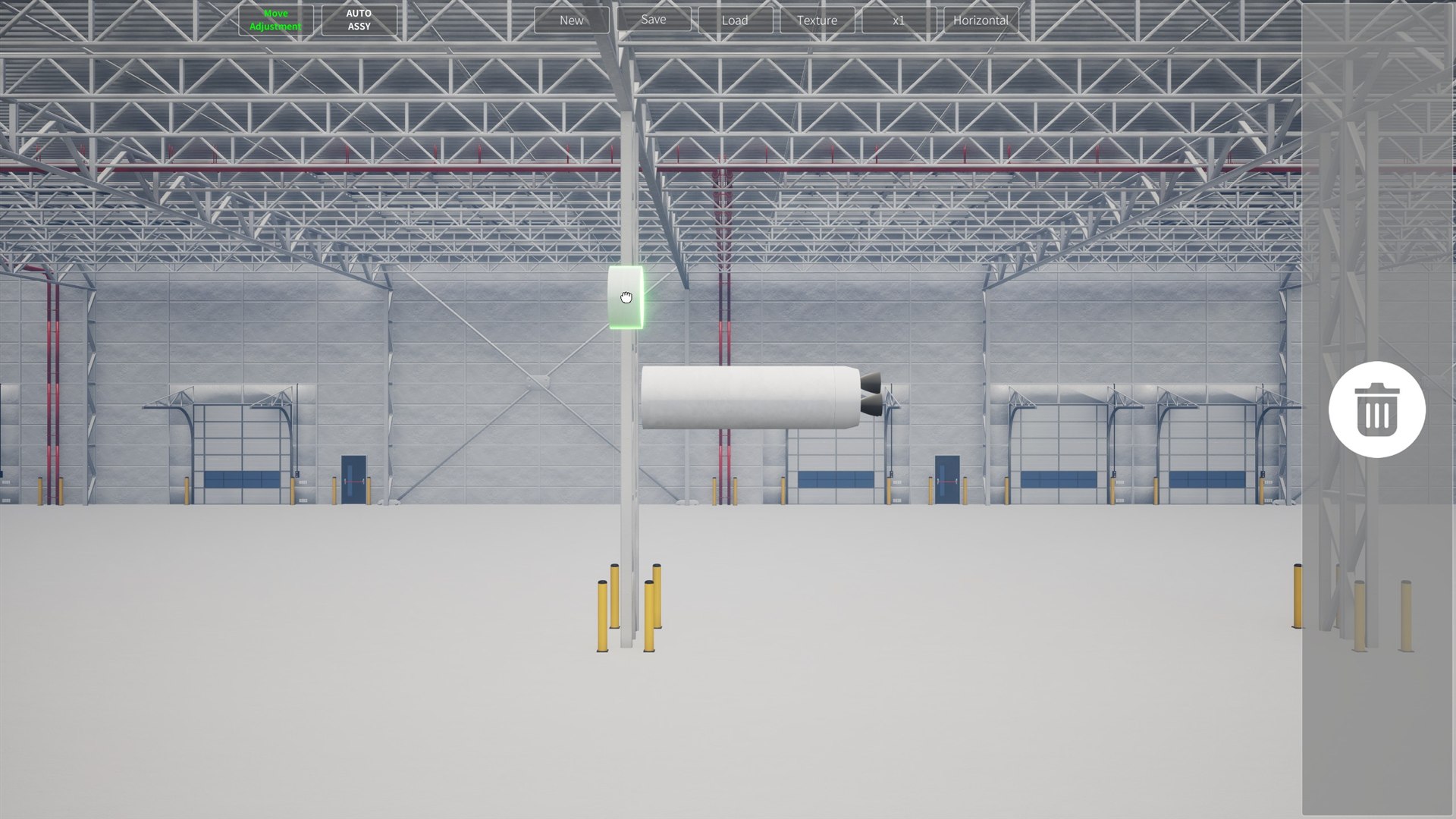
When you left-click a part to grab it, a delete area appears at the right edge of the screen. Move the grabbed part into the delete area to remove it. You can also press the Delete key while holding a part.
Top Toolbar
| Button | Description |
|---|---|
| Move Adjustment (toggle) | Changes how depth is handled while you drag a part. Normally (OFF) a part keeps the depth it had when you grabbed it and moves across the screen at that depth. With it ON, the part is moved with its depth aligned to the centreline of the vehicle, which makes it easier to bring a part that sits far back into line with the middle of the rocket. |
| AUTO ASSY (toggle) | When ON, clicking a part places it automatically on the left of the part currently in place (the first part is placed at the origin). When OFF, you decide where it goes by dragging the mouse after clicking, as described in the basic operations above. |
| New | Removes every part currently placed and starts assembling a new rocket. |
| Save | Saves the rocket you are assembling. |
| Load | Loads a saved rocket. |
| Texture | Opens a dialog for managing the images (custom textures) you can apply to a rocket. You can register images you have made yourself, then view, add and delete them. |
| x1 to x6 | Sets how many copies of a part are placed radially. Use it for side-mounted parts such as boosters. With it set to x2 or higher, placing a part on the side of a target part creates several copies at equal spacing around that part's centreline. Once placed, the copies are treated as a single group. |
| Horizontal / Vertical (toggle) | Switches how the rocket under assembly is displayed. Horizontal lays it down, Vertical stands it up. |
Stage Information
Selecting "Show Stage Information" at the bottom of the screen displays the performance of the current vehicle broken down by stage. Placing an interstage automatically divides the stages at that point. Select the button again to close the panel.
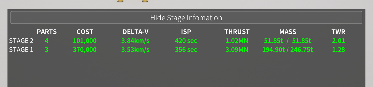
| Item | Description |
|---|---|
| PARTS | The number of parts that make up the stage. |
| COST | The total cost of the parts in the stage. |
| DELTA-V | A guide to how much velocity change the stage can deliver. The larger the value, the more you can alter your orbit. |
| ISP | The specific impulse of the engines, expressed in seconds. It shows how efficiently propellant is converted into thrust. |
| THRUST | The total thrust produced by the engines in the stage. |
| MASS | Shown as "stage mass / total mass": the mass of the stage on its own, and the total mass including the upper stages it has to accelerate. |
| Thrust-to-weight ratio (TWR) | How many times the weight the thrust amounts to. If it is 1.0 or below on the first stage, thrust does not exceed weight and the rocket cannot lift off the ground. |
The current version has no button for switching between sea-level and vacuum performance figures.
Saving and Loading
Save lets you enter a name and description and save the current vehicle. If you edit a vehicle you loaded and then save it, that vehicle's saved data is updated. Saving a newly assembled vehicle from New registers it as a separate vehicle.
Load lets you pick a saved vehicle from a list and load it into the VAB. Only the valid parts connected back to the root part are saved.
Parts Editor
Right-click a placed part to open the Parts Editor on the right of the screen. There you can edit the part's colour, how its material looks, its surface pattern and its orientation. Changes are applied to the part on screen immediately, and are stored per part when you save the vehicle.
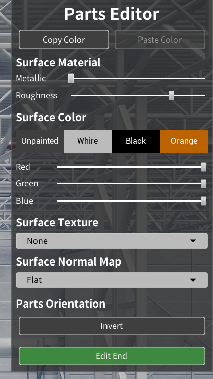
| Item | Description |
|---|---|
| Copy Color | Temporarily copies the colour and surface material settings of the current part. Use it to apply the same appearance to another part. |
| Paste Color | Applies the colour and surface material settings copied with Copy Color to the part being edited. It cannot be selected until something has been copied. |
| Metallic | Adjusts how metallic the surface looks. Higher values make it reflect the surrounding light like metal. |
| Roughness | Adjusts how rough the surface is. Lower values give a stronger gloss; higher values give a softer, more diffuse reflection. |
| Unpainted / White / Black / Orange | The colour presets provided. Unpainted returns the part to its original colour. |
| Red / Green / Blue | Mix your own surface colour with the red, green and blue sliders. |
| Surface Texture | Selects an image to lay over the surface of the part. None uses no image. Custom textures registered from Texture on the top toolbar can also be selected here. |
| Surface Normal Map | Selects the fine surface relief. Flat adds no relief; the other entries add the shading of a surface pattern without changing the shape. |
| Invert | Reverses the front-to-back orientation of the part. Use it when you want an engine, nose cone or similar mounted the other way round. |
| Edit End | Finishes editing and closes the Parts Editor. |
5. Launch and Flight
Launch Preparation
Select a launch site and open "LAUNCH PREPARATION" to choose the launch vehicle and payload to use, and to set the target orbit and flight profile for the automatic launch.
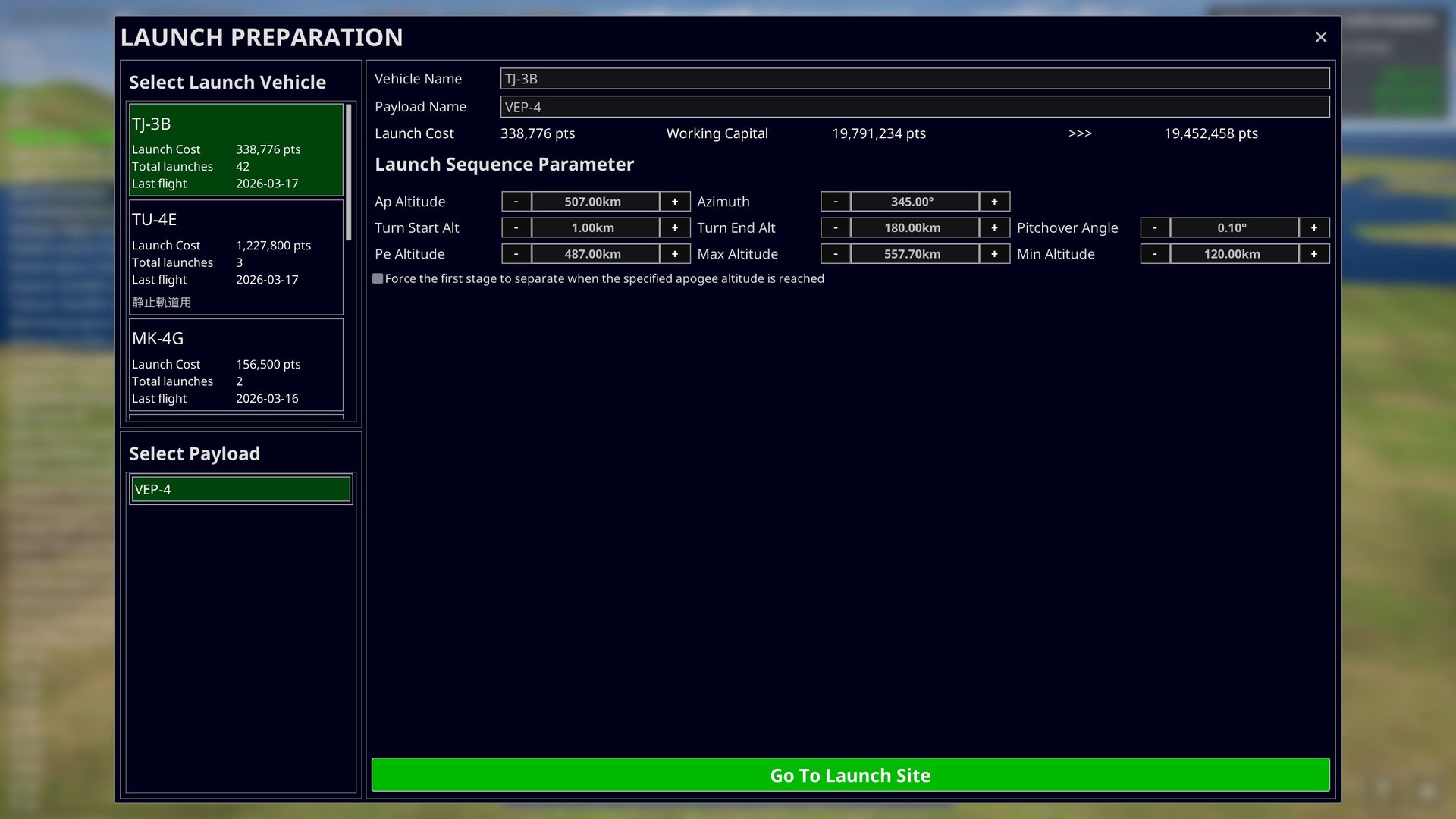
Choose the launch vehicle and payload from the lists on the left. The launch vehicle entry shows its launch cost, the number of times it has flown and the date of its last flight. At the top of the screen you can rename the launch vehicle and the payload, and check the launch cost, your current funds and your funds after the launch. In the current version you can launch even when the funds after launch would be negative.
Launch Sequence Parameter
These set the targets used by the automatic launch. The values are stored per launch vehicle and are reused the next time you select the same vehicle.
| Item | Description |
|---|---|
| Ap Altitude | The target apoapsis altitude of the orbit you are aiming for. During the ascent, the engine is cut off once the apoapsis of the planned orbit reaches this altitude, and the vehicle coasts toward apoapsis. |
| Pe Altitude | The target periapsis altitude of the orbit you are aiming for. The engine is reignited near apoapsis and raises the orbit until the periapsis reaches this altitude. |
| Azimuth | The horizontal direction the vehicle pitches over toward after launch. It is given as 0° for north, 90° for east, 180° for south and 270° for west. The latitude of the launch site and the azimuth together determine the orbital inclination you can reach. |
| Turn Start Alt | The altitude at which the gravity turn begins. The vehicle climbs almost vertically up to this altitude, then rolls to match the azimuth and starts to pitch over gradually. |
| Turn End Alt | The altitude at which the gravity turn ends. The vehicle is brought gradually closer to horizontal as it approaches this altitude. If the apoapsis of the planned orbit reaches the target altitude first, the vehicle moves on to apoapsis adjustment at that point. |
| Pitchover Angle | The angle by which the vehicle first tips away from vertical when the gravity turn begins. Values near 0° start the turn gently from an almost vertical attitude; larger values tip the vehicle over more strongly from an early stage. |
| Max Altitude | The highest apoapsis altitude allowed during periapsis adjustment. If the apoapsis exceeds this value and the periapsis is at the same time above "Min Altitude", the engine is cut off and orbital insertion is completed even though the "Pe Altitude" target has not been reached. |
| Min Altitude | Used together with "Max Altitude": the lowest periapsis altitude at which orbital insertion may be completed. The normal target periapsis is set with "Pe Altitude". |
| Force first stage separation | When "Force the first stage to separate when the specified apoapsis altitude is reached" is enabled, the first stage is jettisoned as soon as the apoapsis of the planned orbit reaches the specified altitude, even if propellant remains. |
Once the settings are ready, select "Go To Launch Site". The chosen launch vehicle and payload are moved to the launch pad and you continue to the launch screen.
Automatic Launch
A launch is carried out automatically all the way to orbital insertion; all you specify is the target orbit. The sequence follows the same flow as a real rocket.
| Phase | What happens |
|---|---|
| 1. Lift-off | The engines ignite. The vehicle leaves the pad the moment thrust exceeds its weight. |
| 2. Vertical climb | The vehicle climbs straight up to about 1 km. |
| 3. Roll (azimuth alignment) | The vehicle rolls to line itself up with the launch azimuth. |
| 4. Gravity turn | As altitude increases the vehicle pitches over gradually and begins accelerating toward the horizontal. |
| 5. Apoapsis adjustment and MECO | Once the apoapsis (Ap) reaches the target altitude the main engine is cut off, followed by stage separation. |
| 6. Coasting | The vehicle coasts up toward apoapsis. Time acceleration is applied automatically during this phase and returns to real time as the reignition approaches. |
| 7. Reignition and periapsis adjustment | Shortly before apoapsis the engine is reignited, raising the periapsis (Pe) to the target altitude and circularising the orbit. |
| 8. Orbital insertion complete | The engine is cut off once the periapsis reaches the target altitude. The launch sequence is over. |
The following events also happen automatically during the flight.
-Booster separation … the boosters are jettisoned when they run out of propellant.
-Fairing separation … the fairing is jettisoned at around 100 km, once the vehicle is clear of the atmosphere.
You are free to change the time acceleration and move the camera during an automatic launch. Just before the interesting moments, such as a separation or a reignition, time acceleration returns to real time automatically.
Manual Control
Select a spacecraft and switch to control mode to fly it directly from the keyboard.
| Action | Key | Description |
|---|---|---|
| Throttle up / down | Left Shift / Left Ctrl | Raises and lowers the thrust in small steps. |
| Throttle max | Z | Takes the thrust straight to 100%. |
| Throttle cut | X | Sets the thrust to 0 (engine cut-off). |
| Pitch | W / S | Points the nose up and down. |
| Yaw | A / D | Points the nose left and right. |
| Roll | Q / E | Rotates the vehicle about its own axis. |
| Stage separation | Space | Jettisons the current stage. |
How quickly the attitude responds depends on the vehicle's moment of inertia and its thrust. Note that a heavy vehicle, or an upper stage with little thrust, will change attitude only slowly.
SAS (Stability Augmentation System)
SAS keeps the vehicle pointed automatically in a direction you choose. The following modes are available.
| Mode | Direction |
|---|---|
| Prograde | The direction of travel. Use it when accelerating to raise your orbit. |
| Retrograde | The opposite of the direction of travel. Use it when slowing down to lower your orbit. |
| Normal | Perpendicular to the orbital plane. Use it to change the orbital inclination. |
| Antinormal | The opposite of Normal. |
| Zenith | Directly away from the centre of the parent body (straight up). |
| Nadir | Toward the centre of the parent body (straight down). |
| Target | The direction of the object set as the target. |
| Antitarget | The opposite of the target direction. |
| Maneuver | The burn direction of the maneuver you have set. |
Velocity-based directions such as Prograde and Retrograde switch automatically:referenced to airspeed (speed relative to the atmosphere) before orbital insertion, and to inertial velocity after it. This always matches the markers shown on the NavBall.
Time Acceleration Rules
The maximum time acceleration is determined automatically by the altitude and flight state of the selected spacecraft. The conditions are tested from the top down, and the first one that applies is used.
| State | Maximum rate |
|---|---|
| Another spacecraft within 200 m | ×1 (real time only) |
| Another spacecraft within 1 km | Up to ×4 |
| Below 1 km (except during launch) | ×1 (real time only) |
| From 1 km up to the edge of the atmosphere, or while the engine is burning | Up to ×4 |
| Well clear of the atmosphere and not burning | Calculated automatically from the orbital period (up to a rate that completes one orbit in roughly 10 seconds) |
- If you had set a rate above the limit, it is automatically reduced to the limit.
- Touchdown and contact between spacecraft are only detected at real time, which is why the limit drops at low altitude and during a close approach. A launch is not subject to contact detection, so you can accelerate up to ×4 from the moment you lift off.
- During an automatic launch, a rate suited to each phase is set automatically (×2 during the gravity turn, ×4 during apoapsis adjustment, up to ×60 while coasting, and so on). If you change the rate yourself, your setting takes priority.
- Just before events such as stage separation, fairing separation and reignition, the rate returns to real time automatically so that you do not miss them.
6. Contracts
Contracts are the goals you complete — a specified flight or mission — in order to earn rewards. The funds and points you earn let you grow your organisation and move on to more demanding missions.
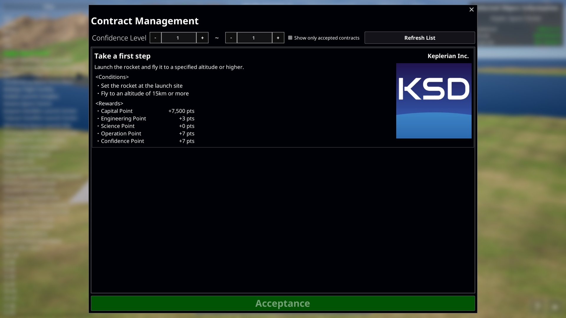
Accepting a Contract
- Open the menu at the bottom right of the screen and select "Contract Management".
- Select the contract you want to look at from the "Contracts List".
- Check the description of the contract, its "<Conditions>" and its "<Rewards>".
- Select "Acceptance" to take the contract on.
Enable "Show only accepted contracts" to see just the contracts you currently have. To give one up, select it and choose "Cancellation of Contract".
Objectives and Completion
Progress on an accepted contract is checked automatically, including during flight. Where a contract has several conditions, all of them must be met.
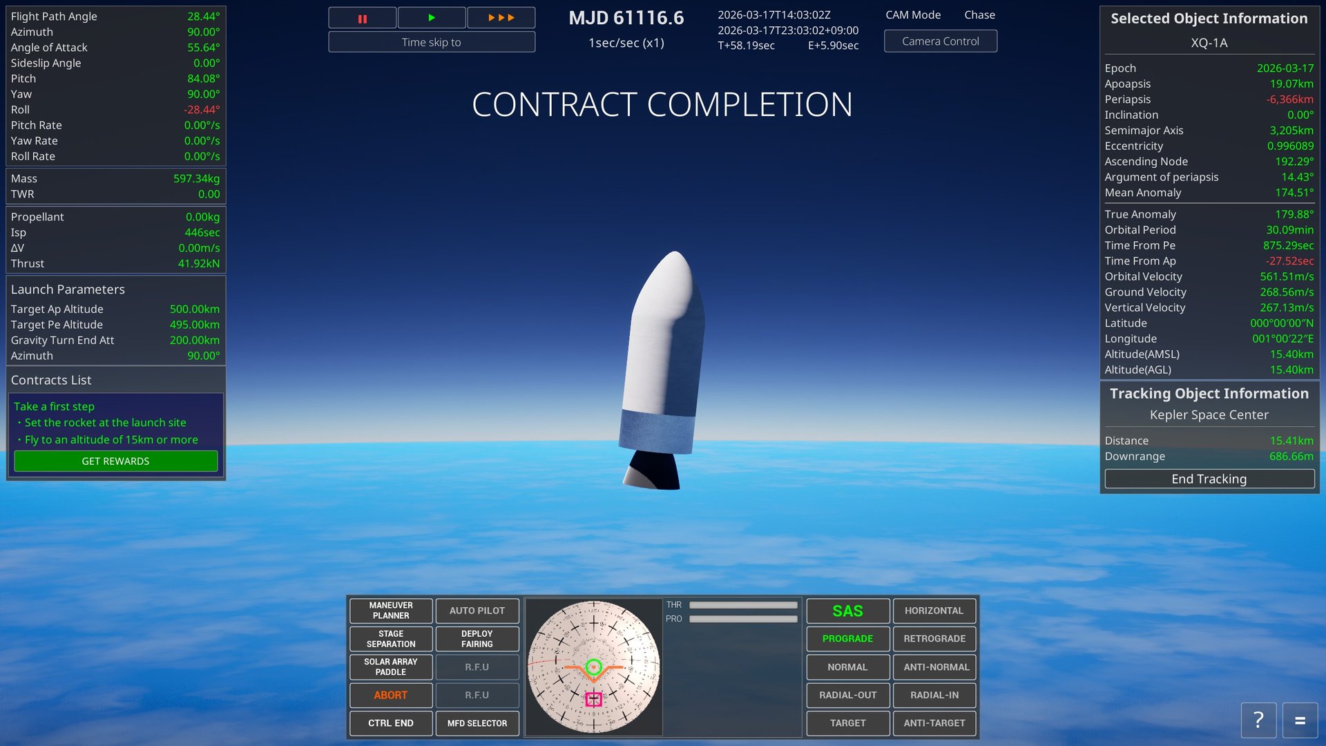
When you complete a contract, a completion screen appears. Select "GET REWARDS" to see the result. In the first contract, "Take a first step", the goal is to place a rocket on the launch pad and reach an altitude of 15 km or more.
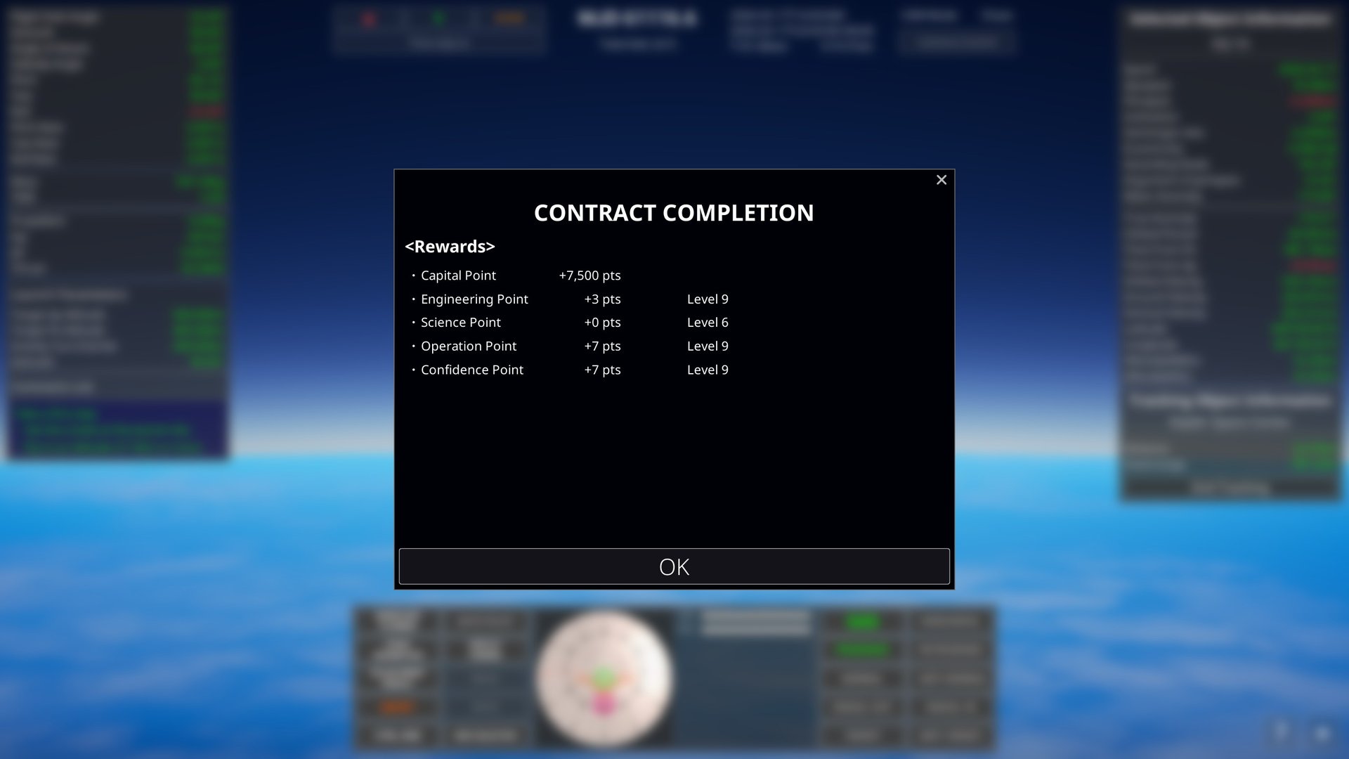
Selecting "GET REWARDS" shows the points you have earned and your current levels. Check them and select "OK" to close the screen.
Rewards
Each contract carries the following rewards. Some of them may be worth 0 points.
| Reward | What it is for |
|---|---|
| Capital Point | Spent as the cost of a launch. It is not needed to build a vehicle itself. |
| Engineering Point | Needed to raise your engineering level and unlock more advanced parts. |
| Science Point | Needed to raise your science level and make certain parts and targets available. |
| Operation Point | Raises your operation level. As it rises, more launch sites become available. |
| Confidence Point | Raises your confidence level. As it rises, more kinds of contract become available to choose from. |
7. Orbital Basics
Keplerian Orbital Elements
The orbit of a spacecraft or a celestial body is described by a set of six numbers, the Keplerian orbital elements. They are where this game gets its name, and they underlie every piece of orbital information in it. The six elements are easier to grasp if you divide them into three groups by what they do.
| Element | Meaning |
|---|---|
| Shape and size of the orbit | |
| Semi-major axis a | The size of the orbit: half of the longer diameter of the ellipse. The larger it is, the higher the orbit, and the orbital period follows from this value. |
| Eccentricity e | How flattened the orbit is. 0 is a perfect circle, and values between 0 and 1 give an ellipse. At 1 or above the orbit no longer closes and the object escapes the parent body's gravity. |
| Orientation of the orbital plane | |
| Inclination i | The tilt of the orbital plane relative to the equatorial plane. 0° orbits above the equator; 90° is a polar orbit passing over the north and south poles. Beyond 90° the orbit is retrograde, running against the body's rotation. |
| Longitude of the ascending node Ω | The direction, measured from the reference direction, of the point where the orbit crosses the equatorial plane from south to north (the ascending node). It fixes which way the tilted orbital plane faces. |
| Argument of periapsis ω | Where the periapsis lies, measured along the orbit from the ascending node. It fixes the orientation of the ellipse within the orbital plane. |
| Position along the orbit | |
| Mean anomaly M | An angle giving where you are within one revolution. It increases at a constant rate with time, and 360° is one complete orbit. |
- The altitudes of the apoapsis (Ap) and periapsis (Pe) follow from the semi-major axis a and the eccentricity e. The target orbit for an automatic launch is likewise given as apoapsis and periapsis altitudes.
- The lowest inclination you can reach directly from a launch is the latitude of the launch site. The closer a launch site is to the equator, the more freedom you have in choosing an orbit.
- Launching toward the east turns the body's rotation speed straight into extra acceleration (about 465 m/s at the Earth's equator). This is why so many launch sites face open sea to the east.
8. Reference
Control Keys
| Control | Keyboard | Mouse | Game Pad |
|---|---|---|---|
| Camera Rotation | I/K/J/L | RMB + Drag | Right stick |
| Camera Move | - | MMB + Drag | - |
| Camera Dolly | Home/End | Wheel | L/R Trigger |
| Camera Zoom | Page Up/Down | - | - |
| Camera Exposure | Insert/Delete | - | - |
| Camera Mode Change | V | MMB + RMB | Back button |
| Camera Orientation *1 | - | LMB + Drag | - |
| Camera Roll *1 | Q/E | - | L/R Shoulder |
| Camera Reset | - | LMB + RMB | Right stick press |
| Map View | M | - | - |
| UI Show/Hide | F2 | - | - |
| SOI Show/Hide | F3 | - | - |
| Quick Save | F5 | - | - |
| Quick Load | F9 | - | - |
| Start Tracking | O | RMB on the list | Y button |
| Open Menu | ESC | - | Start button |
| Open Control Panel *2 | C | - | X button |
| Throttle Max *3 | Z | - | - |
| Throttle Cut *3 | X | - | - |
| Throttle Up *3 | Left Shift | - | - |
| Throttle Down *3 | Left Ctrl | - | - |
| Stage Separation *3 | Space | - | - |
| Roll *3 | Q/E | - | - |
| Pitch *3 | W/S | - | - |
| Yaw *3 | A/D | - | - |
| Debug Console | ALT + F12 | - | - |
*1 : When the camera mode is not "Chase".
*2 : Only while a spacecraft is selected.
*3 : Only in spacecraft control mode.
Launch Sites
The launch sites available in the game. The founding dates and coordinates are the values registered in the game data.
| Launch site | Established | Latitude | Longitude | Notes |
|---|---|---|---|---|
| Kepler Space Center | 1950/01/01 | 0.00° N | 1.00° E | A fictional space centre that appears only in this game. |
| Kennedy Space Center | 1962/07/01 | 28.52° N | 80.65° W | A large launch site long used as the base for lunar exploration, the Space Shuttle and human spaceflight. |
| Cape Canaveral Space Force Station | 1950/07/24 | 28.49° N | 80.58° W | A major launch site used for a wide variety of rockets from the earliest days of spaceflight to the present. |
| SpaceX Starbase | 2002/05/06 | 26.00° N | 97.15° W | A dedicated site for developing, building, testing and launching Starship and Super Heavy. |
| Vandenberg Space Force Base | 1941/01/01 | 34.73° N | 120.56° W | With open ocean to the south, this site suits launches into polar and Sun-synchronous orbits. |
| Wallops Flight Facility | 1945/01/01 | 37.94° N | 75.46° W | A research and test site handling sounding rockets, scientific balloons and small orbital missions. |
| Kodiak Launch Complex | 1998/01/01 | 57.44° N | 152.34° W | A sea-girt launch site suited to high-inclination and polar orbits. |
| Guiana Space Centre | 1964/04/14 | 5.23° N | 52.76° W | Close to the equator, which makes it well placed for geostationary transfer orbits that take advantage of the Earth's rotation. |
| Jiuquan Satellite Launch Center | 1958/01/01 | 40.95° N | 100.29° E | An inland launch site known for crewed spacecraft and low Earth orbit satellites. |
| Taiyuan Satellite Launch Center | 1966/01/01 | 38.84° N | 111.60° E | An inland launch site handling many satellite launches into polar and Sun-synchronous orbits. |
| Wenchang Space Launch Site | 2014/10/18 | 19.61° N | 110.95° E | A coastal, low-latitude site used for large rockets and deep space missions. |
| Xichang Satellite Launch Center | 1982/01/01 | 28.24° N | 102.02° E | A launch site used for geostationary transfer orbit satellites and lunar and planetary probes. |
| Tanegashima Space Center | 1969/10/01 | 30.40° N | 130.98° E | A coastal site with facilities for assembling, testing and launching large rockets. |
| Uchinoura Space Center | 1963/12/09 | 31.25° N | 131.07° E | A launch site among the hills, used to launch and track sounding rockets, science satellites and probes. |
| Hokkaido Spaceport | 2021/04/20 | 42.50° N | 143.44° E | A commercial spaceport open to private users, supporting sounding rockets and future orbital launches. |
| Spaceport Kii | 2021/01/01 | 33.54° N | 135.89° E | A dedicated site built as the launch base for the small solid-fuel rocket KAIROS. |
| Naro Space Center | 2009/06/11 | 34.43° N | 127.53° E | A coastal space centre used to develop and launch rockets such as Naro and Nuri. |
| Sohae Satellite Launching Station | 2012/03/01 | 39.66° N | 124.71° E | A coastal site with satellite launch facilities and large rocket test stands. |
| Baikonur Cosmodrome | 1955/06/02 | 45.96° N | 63.30° E | The long-serving cosmodrome that sent up the first artificial satellite and the first human spaceflight. |
| Plesetsk Cosmodrome | 1957/07/15 | 62.92° N | 40.57° E | A high-latitude cosmodrome well suited to polar and high-inclination orbits. |
| Vostochny Cosmodrome | 2011/08/01 | 51.88° N | 128.33° E | A relatively new cosmodrome supporting launches of Soyuz, Angara and others. |
| Rocket Lab Launch Complex 1 | 2016/09/26 | 39.26° S | 177.87° E | A private launch site operating the Electron rocket, designed for frequent small-satellite launches. |
| Satish Dhawan Space Centre | 1971/10/09 | 13.71° N | 80.23° E | A large space centre with several launch pads, operating the PSLV, GSLV and LVM3. |
| Andøya Space | 1962/08/18 | 69.29° N | 16.02° E | A site with a long record in sounding rockets and atmospheric and auroral research, now with orbital launch facilities as well. |
| Semnan Space Center | 2006/11/02 | 35.23° N | 53.92° E | An inland site used to launch and test small satellite launch vehicles. |
| Palmachim Airbase | 1988/09/19 | 31.90° N | 34.69° E | Known for launching into retrograde orbits, because rockets are sent out over the sea to the west. |
| Aunt Effie's Farm | 1926/03/16 | 42.22° N | 71.81° W | Not a launch site as such, but the field where Robert Goddard launched the world's first liquid-fuelled rocket in 1926. |
Glossary
The main terms used in this manual and in the game.
| Term | Meaning |
|---|---|
| Orbits and flight | |
| Apoapsis (Ap) | The point on an orbit furthest from the parent body. During a launch, accelerating on the way up raises the apoapsis of the planned orbit to the target altitude. |
| Periapsis (Pe) | The point on an orbit closest to the parent body. Accelerating near apoapsis to lift the periapsis clear of the atmosphere gives a stable orbit. |
| Keplerian orbital elements | The six numbers that describe the size, shape and orientation of an orbit and your position along it. For details, see "Keplerian Orbital Elements". |
| Semi-major axis (a) | The value that describes the size of an orbit. It is half of the longer diameter of the ellipse, and it also determines the orbital period. |
| Eccentricity (e) | How flattened an orbit is. 0 is a circle, values above 0 and below 1 give an ellipse, and 1 or more gives an open escape trajectory. |
| Inclination (i) | The tilt of the orbital plane relative to the parent body's equatorial plane. 0° is an equatorial orbit and 90° is a polar orbit. |
| Longitude of the ascending node (LAN / Ω) | The direction of the ascending node, where the orbit crosses the equatorial plane from south to north. It fixes which way the orbital plane faces. |
| Argument of periapsis (ω) | The angle from the ascending node to the periapsis, measured along the orbit. It fixes which way the ellipse points within the orbital plane. |
| Mean anomaly (M) | An angle that relates a body's or spacecraft's position within one orbit to time. |
| SOI (Sphere of Influence) | The region within which a body's gravity is treated as central for orbit calculations. Entering another body's SOI switches the parent body of your orbit. |
| Karman line | The altitude treated as the boundary between the atmosphere and space. In this game, once the periapsis altitude rises above the parent body's Karman line, orbital insertion is judged to be complete. |
| Orbital insertion | Placing a spacecraft into an orbit on which it can keep circling the parent body. In this game it means the state where the periapsis altitude is above the Karman line. |
| Ballistic flight | Flight under gravity alone, with the engines off, before orbital insertion. Left as it is, the spacecraft will fall back to the parent body. |
| Coasting | A stretch of flight with the engine off, where the spacecraft moves under its own velocity and gravity. In an automatic launch it refers to the period between apoapsis adjustment and reignition. |
| Gravity turn | A launch technique in which the vehicle is pitched over gradually as it climbs, using gravity to move smoothly from a vertical climb to horizontal acceleration. |
| Azimuth | The angle giving a direction of travel in the horizontal plane. In this game's launch settings, north is 0°, east 90°, south 180° and west 270°. |
| Circularisation | Accelerating prograde near apoapsis to raise the periapsis and reduce the difference between the two altitudes. |
| Rendezvous | Approaching another spacecraft or object in orbit and matching its position and velocity. |
| ΔV (delta-V) | The velocity change a spacecraft can produce with its propellant, or the velocity change an orbital manoeuvre requires. The larger it is, the bigger the orbital change you can make. |
| Inertial velocity / airspeed | Inertial velocity is measured against space itself; airspeed is measured against the rotating atmosphere. Aerodynamics during launch and the NavBall use airspeed, while orbit calculations use inertial velocity. |
| Vehicles | |
| Thrust | The force with which an engine accelerates a spacecraft. To lift off the ground, thrust must exceed the weight acting on the vehicle. |
| Specific impulse (Isp) | A measure, in seconds, of how efficiently an engine converts propellant into thrust. The higher the value, the more efficient the engine. |
| Thrust-to-weight ratio (TWR) | The ratio of thrust to the weight of the vehicle. At 1.0 or below on the ground, thrust does not exceed weight and the vehicle cannot lift off. |
| Stage | A section of a rocket that is jettisoned in flight. Separating spent engines and tanks makes the remaining vehicle lighter. |
| Booster | An auxiliary motor added to the side of a vehicle, mainly to add thrust in the early part of a launch. It is jettisoned once its propellant runs out. |
| Decoupler | A part that joins stages together and releases them in flight. In the VAB, stages are divided at the position of each decoupler. |
| Fairing | A shroud that protects the payload from air resistance and heating during launch. It is jettisoned once the vehicle is clear of the atmosphere. |
| Payload | The satellite, probe or other cargo a rocket carries. |
| MECO | Short for Main Engine Cut Off. In an automatic launch it happens when the apoapsis of the planned orbit reaches the target altitude. |
| Max Q | The point in flight where dynamic pressure peaks. The aerodynamic load on the vehicle from air density and airspeed is at its greatest here. |
| Screen and controls | |
| NavBall | The instrument that shows the spacecraft's attitude on a sphere, together with reference directions such as the direction of travel, the orbital plane and the target. |
| SAS | The attitude hold function that keeps the spacecraft pointed automatically in a direction you choose. |
| Prograde / Retrograde | Prograde is the direction of travel and Retrograde is its opposite. Accelerating prograde raises the orbit; accelerating retrograde lowers it. |
| Normal / Antinormal | The directions perpendicular to the orbital plane, one either way. Accelerating along them changes the orbital inclination. |
| Zenith / Nadir | Straight up, away from the centre of the parent body, and straight down, toward it. |
| Target / Antitarget | The direction toward the tracking target, and its opposite. |
| Maneuver | The burn direction of an orbital manoeuvre you have set. It can be used as a target direction on the NavBall and with SAS. |
| Map View | The view used to check the whole orbit of the selected object, its apoapsis and periapsis, and its position relative to other objects. |
| Time acceleration | The function that speeds up the passage of in-game time. The maximum rate available depends on your altitude and flight state. |